

Objective:

original globe
Originally my plan is to make a wooden base for the globe to rest on and then somehow pierce 4 holes in to the globe so that it can house 4 Led lights.... so I used a piece of wood that i had from my design class and cut it to pieces to construct my base. Also I wanted to hide the breadboard and the Arduino underneath the wooden base for aesthetic.


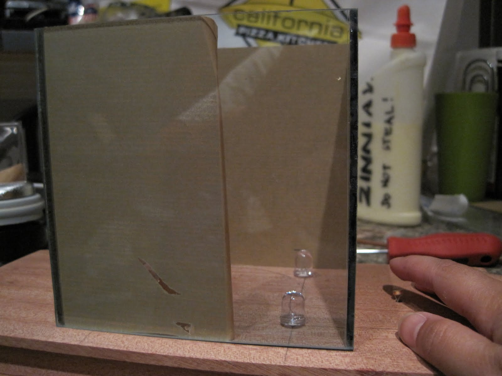
My globe came rolling out of the bag and fell on the floor. My first thought is the buy a new globe, but then i thought that will defeat my objective of this project then i thought about finding another object to work with ...... So after a long deliberation on what to do next, i decided to redesign and create a transparent cover to house whats left of the globe, using Plexiglass......
Construction II:
Parts:
Shuttered Globe, Wood Plank, 2 Transistors, wires, breadboard, arduino, Photo resistors, 4 LED Lights, Plexy glass.
Installation Process:
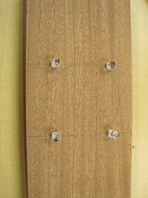
Cut the base and marked the location of the 4 Led lights. In this project i have my Led lights on each corner of my new globe cover. Also marked the location of the photo resistor.
 I soldered the led's endpoint with a longer wires so that i can reach the breadboard and arduinos' pins.then i installed the lights and the arduino on the top of the base.


After all the wiring wirings and the LEDSs are working with Arduino, I constructed the the cover / housing.


Code and Schematic: http://tinyurl.com/crdum6''
/*
* A simple programme that will change the intensity of
* an LED based * on the amount of light incident on
* the photo resistor.
*
*/
//PhotoResistor Pin
int lightPin = 0; //the analog pin the photoresistor is
//connected to
//the photoresistor is not calibrated to any units so
//this is simply a raw sensor value (relative light)
//LED Pin
int ledPin = 9; //the pin the LED is connected to
//we are controlling brightness so
//we use one of the PWM (pulse width
// modulation pins)
void setup()
{
pinMode(ledPin, OUTPUT); //sets the led pin to output
}
/*
* loop() - this function will start after setup
* finishes and then repeat
*/
void loop()
{
int lightLevel = analogRead(lightPin); //Read the
// lightlevel
lightLevel = map(lightLevel, 0, 900, 0, 255);
//adjust the value 0 to 900 to
//span 0 to 255
lightLevel = constrain(lightLevel, 0, 255);//make sure the
//value is betwween
//0 and 255
analogWrite(ledPin, lightLevel); //write the value
}
No comments:
Post a Comment