Wednesday, June 30, 2010

The Skin Bares...

Made up of "Tectonic Plates" that interconnect... The skin itself reveals and the Earth bares the components (metal). The material chosen has translucency so when closed it still interacts as one walks by.

Odd geometries create the plates that when open (via specific sensors per plate), reveal the unknown!


Looking past all the B.S......

If we build it they will come...NO QUESTIONS ASKED!!!


Tuesday, June 29, 2010

Core Vision Exploration...Netbook Style

Well...within one hours of hearing about this core vision software its uploaded and running. Although I did not use an infrared camera I successfully used my webcam and tweaked the settings to get similar results. Currently I am working on how to export this interactivity of movement to LED's versus a screen...

Needed -
Netbook(Computer)...webcam...Partial brain functions...B.A. dining table (for the moment)


If the arduino can interact I will work on a skin development in which this technology will be present within its shell...

Tuesday, June 22, 2010

SYSTEMS


The idea is to simplify the 2' x 2' area into layered systems. By layering systems group members can individually work on code and their own intervention...then they can be combined into a holistic idea.


(4) POSSIBLE SYSTEMS for group members...

1 - Arduino, Motors, Fabric, Muscle wire, some sensor

2 - Arduino, LED Light Show with proximity sensor

3 - Arduino, Interactive play piece..

4 - Arduino, MORE TO COME!!!

ALL SYSTEMS CAN DOUBLE OR TRIPLE WITH FUNCTIONS...
CREATING MULTIPLE INTERACTIVE OPTIONS!!!

SURFACE


THE MOVABLE SURFACE MUST BE TRANSPARENT OR TRANSLUCENT!!!


A possibility of a wire mesh or fabric is possible...

Another possibility to really play with light and incorporate noise could be vinyl plastic...

Both surface options can be layered and colored to create the effects we are going for.


HOW TO MOVE IT?


INTERACTIVE PIECE

How to interact...or make the person activate it?

Possibilities of LED push button (Simon) activater
... switch puzzles
... interactive sports ball to bounce and activate
... grip handles for force with movement
... the surface itself can be touched and moved via the touch


THE IDEA IS TO CREATE A MOVEABLE INTERACTIVE WALL w/ MINIMALISTIC ELECTRONICS...

WORKING WITH LAYERS...
AND NOT w/ TOO MANY MOTORS


LET THE SKETCHING BEGIN!!!!!!!!!!!!!!!!!!!!!!!!!!!!!!!!!!!!!!!!!!!!!!!!!!!!

Ideas for the next Project

I want to do something with motors, lots of motors. My thinking, after chatting with Brennen, is we should do a game, like "Simon says" where the audience tries to copy or repeat a series of actions done by the "box" using touch sensors and LEDs. My next idea is using photo sensors and better motion sensors and muscle wire to create an interactive jelly fish or fish tank something like that. Hopefully other peps in the group have some more ideas.

Thursday, June 17, 2010

Posting Settings Design Monetize View Blog New Post Edit Posts Edit Pages


By using the code keep LED on after button is released I was able to add a photo sensor with the push button to achieve what I wanted. The only issues I am having is not being able to control motors on this code and inverting the sensor to turn on when lights are off versus when they are on.

www.makezine.com/getstartedarduino


Within the next week hopefully the code can be redone to figure out the issues...

// Example 03A: Turn on LED when the button is pressed  // and keep it on after it is released  // // Copy and paste this example into an empty Arduino sketch  #define LED  13  // the pin for the LED  #define BUTTON 7 // the input pin where the                  // pushbutton is connected int val = 0;     // val will be used to store the state                  // of the input pin  int state = 0;   // 0 = LED off while 1 = LED on   void setup() {    pinMode(LED, OUTPUT);   // tell Arduino LED is an output    pinMode(BUTTON, INPUT); // and BUTTON is an input  }    void loop() {    val = digitalRead(BUTTON); // read input value and store it     // check if the input is HIGH (button pressed)    // and change the state    if (val == HIGH) {      state = 1 - state;    }      if (state == 1) {           digitalWrite(LED, HIGH); // turn LED ON    } else {      digitalWrite(LED, LOW);    }  } 

Once again with this code my LED's are running 010101010101010 on and off constantly... I am only achieving half brightness.


My new Light Monster

So after Tuesday's presentations I decided to recreate my light project, since the last one failed. I went to the Dollar store for inspiration and found a small monster truck toy. I took it apart...and so it began. I already had a PIR sensor so I thought it would be funny to make a critter that "ran" at you when you needed some light. I looked online for code that would make the PIR sensor behave the way I wanted. I found code that gave the PIR appropriate delays. Thanks
Kristian Gohlke / krigoo (_) gmail (_) com / http://krx.at
* @date: 3. September 2006

So the original code looks like this
//VARS
//the time we give the sensor to calibrate (10-60 secs according to the datasheet)
int calibrationTime = 30;

//the time when the sensor outputs a low impulse
long unsigned int lowIn;

//the amount of milliseconds the sensor has to be low
//before we assume all motion has stopped
long unsigned int pause = 5000;

boolean lockLow = true;
boolean takeLowTime;

int pirPin = 3; //the digital pin connected to the PIR sensor's output
int ledPin = 13;


/////////////////////////////
//SETUP
void setup(){
Serial.begin(9600);
pinMode(pirPin, INPUT);
pinMode(ledPin, OUTPUT);
digitalWrite(pirPin, LOW);

//give the sensor some time to calibrate
Serial.print("calibrating sensor ");
for(int i = 0; i < locklow =" false;" takelowtime =" true;" lowin =" millis();" takelowtime =" false;"> pause){
//makes sure this block of code is only executed again after
//a new motion sequence has been detected
lockLow = true;
Serial.print("motion ended at "); //output
Serial.print((millis() - pause)/1000);
Serial.println(" sec");
delay(50);
}
}


Then I changed a few things to accommodate my motor and LEDs
New code is
int calibrationTime = 30;

//the time when the sensor outputs a low impulse
long unsigned int lowIn;

//the amount of milliseconds the sensor has to be low
//before we assume all motion has stopped
long unsigned int pause = 3000;

boolean lockLow = true;
boolean takeLowTime;

int pirPin = 3; //the digital pin connected to the PIR sensor's output
int motorPin = 13; //the digital pin connected to the motor's output
int ledPin = 8; //the digital pin connected to the led output
int led2Pin = 10; //the digital pin connected to the led output


/////////////////////////////
//SETUP
void setup(){
Serial.begin(9600);
pinMode(pirPin, INPUT);
pinMode(motorPin, OUTPUT);
pinMode(ledPin, OUTPUT);
pinMode(led2Pin, OUTPUT);
digitalWrite(pirPin, LOW);

//give the sensor some time to calibrate
Serial.print("calibrating sensor ");
for(int i = 0; i < locklow =" false;" takelowtime =" true;" lowin =" millis();" takelowtime =" false;"> pause){
//makes sure this block of code is only executed again after
//a new motion sequence has been detected
lockLow = true;
Serial.print("motion ended at "); //output
Serial.print((millis() - pause)/1000);
Serial.println(" sec");
delay(50);
}
}
}
}
I set up the breadboard like this...
And put it all together.


And the final monster


Tuesday, June 15, 2010

I killed it!

fried my inverter with a 9V.
so i got everything connected but I failed to understand the sensitivity of electronics and power 6VDC is not = 9VDC. Going to get new inverter and try again.

Arduino Lamp Project


Objective:
To create or to develop an already existing object.
On this project, I have a simple Idea. I wanted to enhance or modify an object's purpose, ability, and usage by applying what we learned about Arduino's programming and coding abilities.... So i searched around my house, and i found a last minute gift, a "2008 Graduation Globe" that I onced gave it to my sister as a graduation gift. ( she never liked it). I thought about how can i apply to project to this object....well i thought about... what if i put Led ligths inside the globe and also those led light can be controlled? meaning if the room is dark, it turns on and if its not needed the Led's turn's of automatically.

original globe

Construction:

Originally my plan is to make a wooden base for the globe to rest on and then somehow pierce 4 holes in to the globe so that it can house 4 Led lights.... so I used a piece of wood that i had from my design class and cut it to pieces to construct my base. Also I wanted to hide the breadboard and the Arduino underneath the wooden base for aesthetic.


I went to my School's wood shop to cut my base... After i had all my pieces sized and cut, I put everything in a plastic bag, and I headed back to the studio so i can glue and put them together ....
As soon as i laid my bag with all my stuff in it on the table,
" THE UNIMAGINABLE ????? HAPPENED"


My globe came rolling out of the bag and fell on the floor. My first thought is the buy a new globe, but then i thought that will defeat my objective of this project then i thought about finding another object to work with ...... So after a long deliberation on what to do next, i decided to redesign and create a transparent cover to house whats left of the globe, using Plexiglass......


Construction II:

Parts:

Shuttered Globe, Wood Plank, 2 Transistors, wires, breadboard, arduino, Photo resistors, 4 LED Lights, Plexy glass.

Installation Process:

Cut the base and marked the location of the 4 Led lights. In this project i have my Led lights on each corner of my new globe cover. Also marked the location of the photo resistor.

I soldered the led's endpoint with a longer wires so that i can reach the breadboard and arduinos' pins.then i installed the lights and the arduino on the top of the base.


After all the wiring wirings and the LEDSs are working with Arduino, I constructed the the cover / housing.


Test if the LED lights are working with the Photo Resistor


Final Modified Product


Code and Schematic: http://tinyurl.com/crdum6''

/*
* A simple programme that will change the intensity of
* an LED based * on the amount of light incident on
* the photo resistor.
*
*/
//PhotoResistor Pin
int lightPin = 0; //the analog pin the photoresistor is
//connected to
//the photoresistor is not calibrated to any units so
//this is simply a raw sensor value (relative light)
//LED Pin
int ledPin = 9; //the pin the LED is connected to
//we are controlling brightness so
//we use one of the PWM (pulse width
// modulation pins)
void setup()
{
pinMode(ledPin, OUTPUT); //sets the led pin to output
}
/*
* loop() - this function will start after setup
* finishes and then repeat
*/
void loop()
{
int lightLevel = analogRead(lightPin); //Read the
// lightlevel
lightLevel = map(lightLevel, 0, 900, 0, 255);
//adjust the value 0 to 900 to
//span 0 to 255
lightLevel = constrain(lightLevel, 0, 255);//make sure the
//value is betwween
//0 and 255
analogWrite(ledPin, lightLevel); //write the value
}

Sunday, June 13, 2010

combined both codes and added a little of my handy work :-)

so i combined both the photo cell and the light pattern codes together. i tried to alter the code in a way so that the photo cell would recognize the PWM pins (pulse with modulation pins). the ORANGE would be my handy work, The RED would be the photocells code. My error is in The Colors of the rainbow because.....well its just...you know!!!!


/*Fireflies*/

int value;
int pwmPin = 11; // light connected to digital pin 11-- I just chose an initial value
//int ledpin2 = 9;
long time=0;
int period = 500;
int i = 0;
long blink_delay = 1000; // these must be declared as long due to the random() operation
long blink = 3;
long random_led = 55;
const byte pwmPins [] = {3, 5, 6, 9, 10, 11};

int lightpin = 0; //the ana log pin the
//photoresistor is
//connected to
//the photo resistor is not
//calibrated to any units so
//this is simply a raw sensor value (relative light)
//LED pin
int pwmpin= 11;//the pin the LED is conneced to
//we are conrtolling the brigtness so
//we use one of the PWM (pulse
//width modulation pins)
int pwmpin = 5

int pwmpin = 6

int pwmpin = 9

int pwmpin = 10

int pwmpin = 3


void setup()
{
pinMode(pwmpin, OUTPUT); //sets the led pin to
//output //nothing to setup
}

void loop()

{
int lightLevel = analogRead(lightpin); //Read the
// light level
lightLevel = map(lightLevel, 0, 900, 0, 255);
//adjust the value 0 to 900 to
lightLevel = constrain(lightLevel, 0, 255);
//make sure the value is between 0 and 255
analogWrite(ledpin, lightLevel); //Wright the value
}
{
int lightLevel = analogRead(lightpin); //Read the
// light level
lightLevel = map(lightLevel, 0, 900, 0, 255);
//adjust the value 0 to 900 to
lightLevel = constrain(lightLevel, 0, 255);
//make sure the value is between 0 and 255
analogWrite(ledpin, lightLevel); //Wright the value
}

{
choose_firefly();
fade();

blink_delay = random(500, 4001);
delay(blink_delay);
blink = random(2, 5);

}
void fade()
{
for(i=0; i<255;)
{
time = i;
value = abs(-127+127*cos(4*PI/period*i)); //the -127 value shifts the cosine curve negative with a zero initial value; abs shifts everything positive
analogWrite(pwmPin, value); // sets the value (range from 0 to 255)
delay(blink);
i++;
}
}

void choose_firefly()
{
pwmPin = pwmPins [random (0, 6)];
}

but apparentlly my work was "UNQUALIFIED"

error: expected unqualified-id before numeric constant In function 'void loop()': At global scope:

the mistake wasn't in organization but the Arduino is not recognizing or not accepting something in the code, to my understanding.

could use a little input........

otherwise I'm just stuck with a light show.

0101010101010101010101010

After adding a serial print to the code I was able to figure out that my LEDs are constantly turning on and off (0101010101010). It is happening sooooo fast that the human eye can not detect it and it gives the illusion that the LEDs are always on. Since they are turning on and off at a rapid pace they are not "putting out" the brightness they should be. The serial print assisted in finding the problem but I CANNOT FIX IT!!!

making an arduino nightlight continued

after hooking up the photo cell, then i working on the like LED lights


horizontally i hooked up multiple LEDs and the wires like the yellow one you see, those wires are hooked up to the digital PWM numbers (3, 5, 6, 9, 10, 11)


then i have 2 codes that i followed
First the Photo cell

/*
*A simple Programme that will change the
*intensity of an LED based on the amount of
* light incident on the photo resistor.
*
*/

//photoresistor pin
int lightpin = 0; //the ana log pin the
//photoresistor is
//connected to
//the photo resistor is not
//calibrated to any units so
//this is simply a raw sensor value (relative light)
//LED pin
int ledpin = 9;//the pin the LED is conneced to
//we are conrtolling the brigtness so
//we use one of the PWM (pulse
//width modulation pins)

void setup()
{
pinMode(ledpin, OUTPUT); //sets the led pin to
//output
}
/* loop() - this funtion will start after setup
*finishes and then repeat
*/
void loop()
{
int lightLevel = analogRead(lightpin); //Read the
// light level
lightLevel = map(lightLevel, 0, 900, 0, 255);
//adjust the value 0 to 900 to
lightLevel = constrain(lightLevel, 0, 255);
//make sure the value is between 0 and 255
analogWrite(ledpin, lightLevel); //Wright the value
}


Then i worked with the LED pattern code


/*This sketch is intended to approximate the blinking of fireflies. It varies the delay between
blinks and varies the total blink time. I've used the random() function to vary which PWM output
is chosen for the next blink.
Hope you get some enjoyment out of it. I created it as a fun night light for my kids.
Chad Richardson -- Chad@ChadsCustomWood.net
*/


int value;
int pwmPin = 11; // light connected to digital pin 11-- I just chose an initial value
//int ledpin2 = 9;
long time=0;
int period = 500;
int i = 0;
long blink_delay = 1000; // these must be declared as long due to the random() operation
long blink = 3;
long random_led = 55;
const byte pwmPins [] = {3, 5, 6, 9, 10, 11};

void setup()
{ //nothing to setup
}

void loop()
{
choose_firefly();
fade();

blink_delay = random(500, 4001);
delay(blink_delay);
blink = random(2, 5);

}
void fade()
{
for(i=0; i<255;)
{
time = i;
value = abs(-127+127*cos(4*PI/period*i)); //the -127 value shifts the cosine curve negative with a zero initial value; abs shifts everything positive
analogWrite(pwmPin, value); // sets the value (range from 0 to 255)
delay(blink);
i++;
}
}

void choose_firefly()
{
pwmPin = pwmPins [random (0, 6)];
}


making an arduino nightlight

i know some people have made the arduino night light by using a photo cell, but the lights function just turns on and off, so i found an code thats able to play with 6 LED and randomly lights them up; the only thing is i'm having trouble combining the code or maybe possibly my connection, but im pretty sure its correct. but here is the generall idea of how i connected the photo cell with the light effects called "fireflies"


first the photo cell

Saturday, June 12, 2010

so I'm trying to write some code, and i might say it is a pain in the butt if you don't have it the way Arduino wants it to look like, so i thought of the weirdest thing (i Googled my errors) that is right ladies and gentlemen!!!Google it!!!! for anyone who's coming up with error all the time and wants to know how to correct those mistakes. this guy on this link know what he's talking about (Someoneknows) knows !!!!!

http://diyroboticslab.wordpress.com/2009/06/05/correcting-arduino-compiler-errors/

playing with arduino servo motors and potentiometers

i was playing around with ideas and i was using a 10k ohm potentiometer and a servo motor. the most problem i had with this was making a the servo motor and mechanism to move a sliding door of some sort in this small compartment i made. it didn't turn out to well and it was poorly crafted. on top of that. i wanted to create a switch that would light up the inside. so the person was able to see.

here is how i hooked up the servo with the potentiometer on the arduino

My first arduino attempt


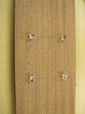
with my first Arduino attempt, i messed around with button and a LED, its suppose to control the button LED functions with the simple press of the button that is stated from the reading "Getting Started with Arduino." After that, i uploaded a sketch example from the arduino program to make the led blink or stay on by command; by reading that, the sketch stated how to manipulate the LED function by changing its digital write (the actions of the LED) from the when it turns on and off as it blinks. by changing its actions, i messed around with its Delay numbers later learning that the LED's blink at a thousandth of a second.

//example of what i was messing with to command the LEDS with in the script thats written in RED

/*
Blink

Turns on an LED on for one second, then off for one second, repeatedly.

The circuit:
* LED connected from digital pin 13 to ground.

* Note: On most Arduino boards, there is already an LED on the board
connected to pin 13, so you don't need any extra components for this example.


Created 1 June 2005
By David Cuartielles

http://arduino.cc/en/Tutorial/Blink

based on an orginal by H. Barragan for the Wiring i/o board

*/

int ledPin = 13; // LED connected to digital pin 13

// The setup() method runs once, when the sketch starts

void setup() {
// initialize the digital pin as an output:
pinMode(ledPin, OUTPUT);
}

// the loop() method runs over and over again,
// as long as the Arduino has power

void loop()
{
digitalWrite(ledPin, HIGH); // set the LED on
delay(1000); // wait for a second
digitalWrite(ledPin, LOW); // set the LED off
delay(1000); // wait for a second
}


the lower the number the faster the LEDs respond in turning on and off. the higher the longer is takes it to respond.


Wednesday, June 9, 2010

Lamp In Progress

"The Monster Lamp" is ready! I could not figure out the code to run the motors but hopefully during our Thursday get together I can reprogram the arduino to activate the motors.
Within a few days of playing with the arduino I feel I am more than qualified to wire up an entire model with LED's activated by sensors. Oh yeah!!!

THIS IS ONE OF THE BEST CLASSES I HAVE EVER TAKEN!!! Good Sh*t Mark!

Code Issues

Combining code is becoming an issue with no basic in class introduction. I am positive that I am not the only one who needs help (where is the almighty Matt when you need him) ...oh well...it will eventually come together!!!

Rock On Monster Lamp!!!

Ok, so this is fun again!

Thanks, Matt Doll. So I figured out the things I didn't know. Some things I read but didn't understand, like if, then statements in code, and + - and output input stuff. Now my little El Wire light won't fry my arduino. Cool.

Tuesday, June 8, 2010

Progress with Play

Currently I am using the keep LED on after button is released command to run a push button and a photo sensor...http://makezine.com/getstartedarduino/

With a 9 volt battery connected to the arduino... it is now programmed and can be inserted in anything to utilize the programmed commands....gnarley!!!

Next is integrating a motor etc. to begin the movement of something... here we go...

Skycraft Blasty Blast!!!

For those of you who have not yet made it to Orlando...it is a must. The store is entirely unorganized but has every possible motor or toy to manipulate and play with. Having an idea of what you need would be better than going in as I did and buying the whole store. I will be back...

Saturday, June 5, 2010

this isn't fun anymore

When is Mark coming back?????I am having so many problems. First i don't understand...anything. i looked online, not a good source for trying to understand this stuff, i guess it is great if you have a basic understanding of how this stuff is supposed to work, but i don't. i can't even grasp where things are supposed to go, (pir sensor to bread board) looked online but too complicated. there are diagrams but then i have to look up the symbols in the diagrams. the only thing i have been successful at is blink!! when is our light due? thursday? i can't even hook up the pir sensor. I AM SCREWED!! if anyne is having any success please call me. 407-879-2135